100 Hp Dc Motor Wiring Diagram 4 Wire
HVAC Condenser Fan Motor Wiring Diagram. Motor Model Prefix HP KW.

3 Awesome Life Hacks With Dc Motor Youtube Useful Life Hacks Life Hacks Electronics Projects Diy
The supply voltage is either 240 volts alternating current vac or 480 vac.

100 hp dc motor wiring diagram 4 wire. The first component is symbol that indicate electrical element in the circuit. Diagram courtesy of Emerson New techs have a common question of how to wire a condensing fan motor for 3 vs. AS-183 wiring diagram with switch.
Damage will occur if the motor is operated with load for more. Use figure 2 if your motor has a dual voltage shunt field. I use a vacuum motor electric lawn mower and treadmill motors to demonstration some cheap options for speed control and wiring to the wall.
The other thing that you will locate a circuit diagram. You will smoke that motor if you hook the motor field to F and F- as that will put 200VDC on your 100VDC motor field windings if you are supplying 230VAC to the drive. L1 and F- are correct for a 100V field on a 230V supply but your motor armature is showing it is only 75 VDC which would be closer to a 120VAC supply.
2-11 in which vector 1 is 120 degrees in advance of vector 2 and the phase sequence is 1 2 3. Finally this guide is intended to be used as a general overview of common condenser unit wiring schematics. Some have 2 wires.
Wiring a dc motor and universal motor for speed control. The other thing that you will get a circuit diagram. Not all 4 wire motors are Armature Voltage controlled.
4 wire reversible PSC motor. AC80 AC90 AC100 single phase motors. Motor Wiring Diagram DC.
Great for torque at all speeds4 wires to the motor. Dc motor wiring diagram. AC65 single phase motors.
There are two things which are going to be present in any Single Phase Motor Wiring Diagram With Capacitor. Motor Wiring Diagram US. The first element is symbol that indicate electrical element from the circuit.
For a visual picture of typical wiring configurations reference the following guide. AC80 AC90 AC100 single phase motors. Minimum Wire Size Chart Gauge - Copper Wire Chart D Motor HP Volts Phase Distance in Feet from Motor to Service Panel Breaker Size Amps 0-50 50-100 100-150 150-200 200-300 033 115230 1 1414 1414 1214 1014 814 1515 05 115230 1 1414 1214 1014 814 612 1515.
Other fans as shown Brown Black Blue M 1 GreenY ellow Brown Cap Black CE31 only Single phase AC motor with capacitor Blue or Grey A N SILDES These diagrams mainly apply to EXTERNAL ROTOR MOTORSbut some standard frame induction motor. ELECTRICAL MOTORS 12 Lead Dual Voltage Wye StartDelta Run Both Voltages or 6 Lead Single Voltage Wye StartDelta Run Motors designed by US Motors for Wye Start Delta Run may also be used for across the line starting using only the Delta connection. 1 WIRING DIAGRAM Diagram ER4 1 WIRING DIAGRAMS M 1 LNE 3 active wires plus auto-reset thermal contacts Codes.
These connections are in accordance with NEMA MG-1 and American Standards Publication 06. Motor Connections Your motor will be internally connected according to one of the diagrams shown below. 2 run to the shunt-field current 2 run to the armature.
There are two things which are going to be found in almost any Mercury Outboard Wiring Diagram Schematic. 3 wire 3 phase motor. Industry wide the 480 volt 3 phase motor is the most common of all electric motors.
AC65 AC80 AC90 AC100 three phase motors. This tech tip is a quick one on the difference between wiring universal condenser fan motors and why brown. A circuit is usually composed by many components.
Leeson motor wiring diagram collections of leeson motor wiring schematic gallery. Jesse Grandbois submitted this tech tip to help make it simple. Use figure 1 if your motor has a single voltage shunt field.
A circuit is usually composed by several components. Bodine gearmotor stock model 0670 type 42R-5N. Time lapse of schematic diagram drawn into a wire diagram and the wiring of the magnetic motor starter.
DC motor with Armature-voltage DC Motor Control. Electric Motor Wire Marking Connections. Vary the voltage applied to the armature vary the speed.
How the wires are interconnected dictates the voltage being supplied to the motor. Treadmill Motor Wiring Diagram 4 Wire Motor Diagram Wiring Diagram Article Review Treadmill Motor Wiring Diagram Lathe Modification Variable Speed Treadmill Dc Motor Treadmill Motor Wiring Diagram 3 Hp Leili Treadmill Motor L 318100 Special Purpose Dc Motors Dc. Identify the wire colors and confirm that you have a 4-wire-reversible PSC permanent split capacitor motor or gearmotor.
Terminal markings and internal wiring diagrams single phase and POLYPHASE MOTORS MEETING NEMA STANDARDS See Fig. 4 wire reversible PSC motor with a triple pole double throw switch. Use figure 1 if your motor has a single voltage shunt field.
For specific Leeson Motor Connections go to their website and input the Leeson catalog in the review box you will find connection data dimensions name plate data etc. Instructions for Wiring or Reversing a 4-Wire AC Gearmotor or Motor. Some condenser fan motors wire to a circuit board while others use proprietary plugs for their connectors.
DC Permanent Magnet with PWM controller Great for torque at all speeds2 wires to the motor Usually.

Motor Wiring Diagrams Groschopp

How To Wire Off Delay Timer Electrical Wiring Colours Timer Electrical Projects

Pin On Our Featured Electric Motors And Drives

Image Result For Wiring Diagram For Reversing Drum Switch Wiring Diagram Diagram Switch

Comparison Between 1 Phase And 3 Phase Motors Motor Hp Input Voltage F L Amps Breaker Size Min Copper Electrical Projects Breakers Electrical Engineering

General Electric Voltage Regulator Wiring Diagram Schematic And Wiring Diagram Voltage Regulator Motorcycle Wiring Electrical Circuit Diagram
Wiring Diagram Of Washing Machine Bookingritzcarlton Info Washing Machine And Dryer Samsung Washing Machine Washing Machine Motor

10 Electric Motor Reversing Switch Wiring Diagram Wiring Diagram Wiringg Net Circuit Diagram Electrical Circuit Diagram Capacitor

Wiring Diagram Wiringg Net In 2021 Electric Motor Wiring Diagram Electrical Circuit Diagram

Update 3 How To Build The Simplest Dc Motor Speed Controller Using Mosfet And Potentiometer Youtube Motor Speed Circuit Diagram Diy Electrical

Honda Cd175 Wiring Diagram Motorcycle Wiring Electrical Wiring Diagram Electrical Diagram

Fluke Tem7 7 Gif 412 293 Electrical Engineering Books Electrical Circuit Diagram Electrical Engineering Projects
Diagram Motor Wiring Diagram 4 Wire Full Version Hd Quality 4 Wire Diagramman Prolococusanese It

4 Creative Things From Electric Motors That You May Not Know Youtube Electric Motor Electricity Electronics Projects
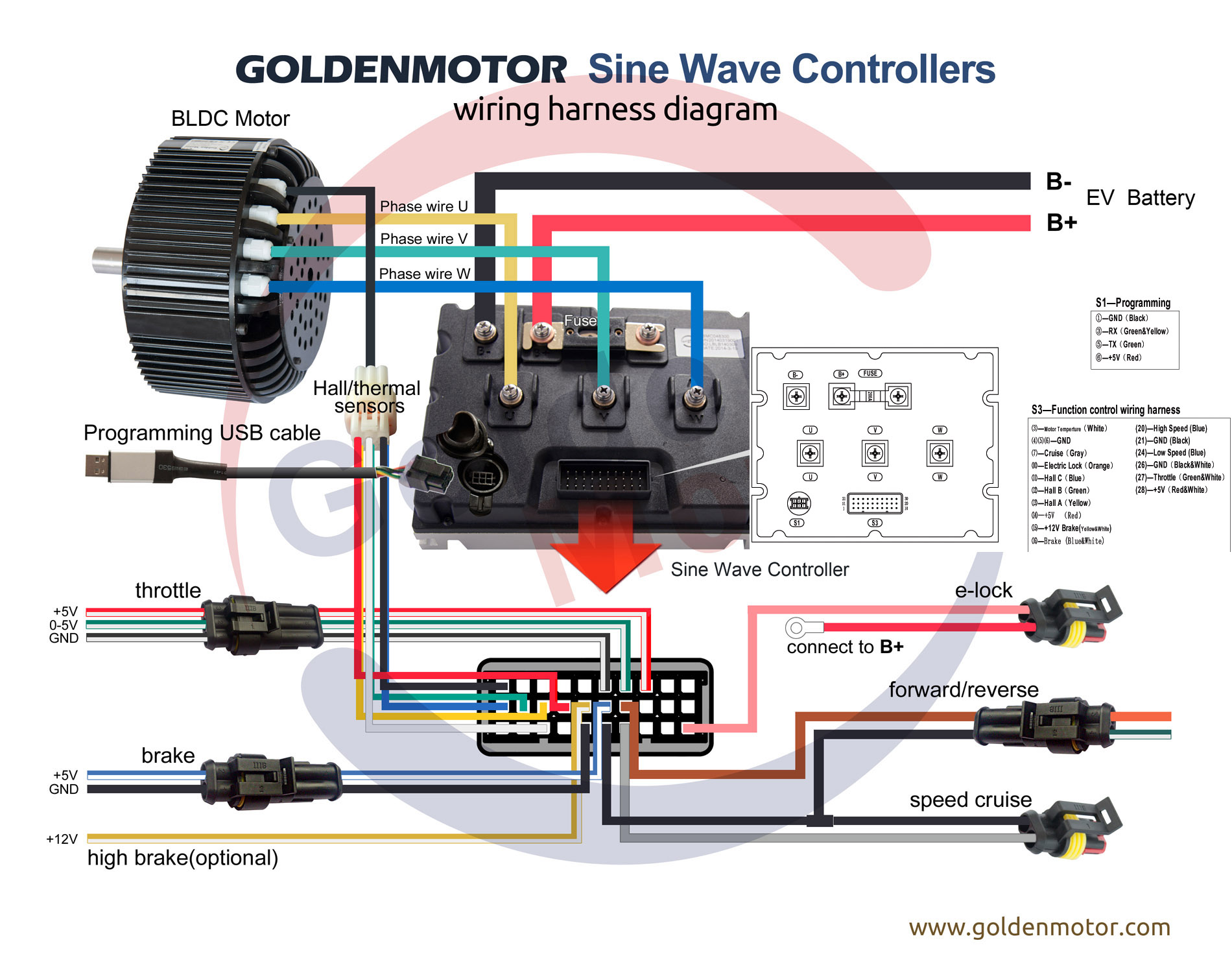
Brushless Motors Bldc Motor Sensorless Motor Motor Controllers Foc Controller Field Oriented Control Brushless Motor Controller Bldc Controller Axial Flux Brushless Motor Golden Gmx

Wiring Color Codes For Dc Circuits Ignition Cdi Circuit For Two Wheelers Homemade Circuit Project Electronic Circuit Projects Ignite Circuit Projects

Engine Wiring Help Diy Go Kart Forum Motorcycle Wiring Diy Go Kart Electrical Wiring Diagram

New 2 Pole 3 Phase Motor Wiring Diagram Baldor Motors Wiring Electric Motor Wiring Electric Motor Wiring Diagram Wiring Diagram

24v 250w Motor Brush Speed Controller For Electric Bike Bicycle Scooter This Item Is One Controller Fo Black Headlights Electric Bike Bicycles Black And Red