Rx1 Rc Plus Wiring Diagram
Follow our SecurityTech Channel. - CAM Control feature may not work depending on UART3 usage OK if not used at all.
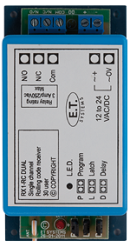
Et Systems Rx1 Rc Code Hopping Receiver Homesecurity1st
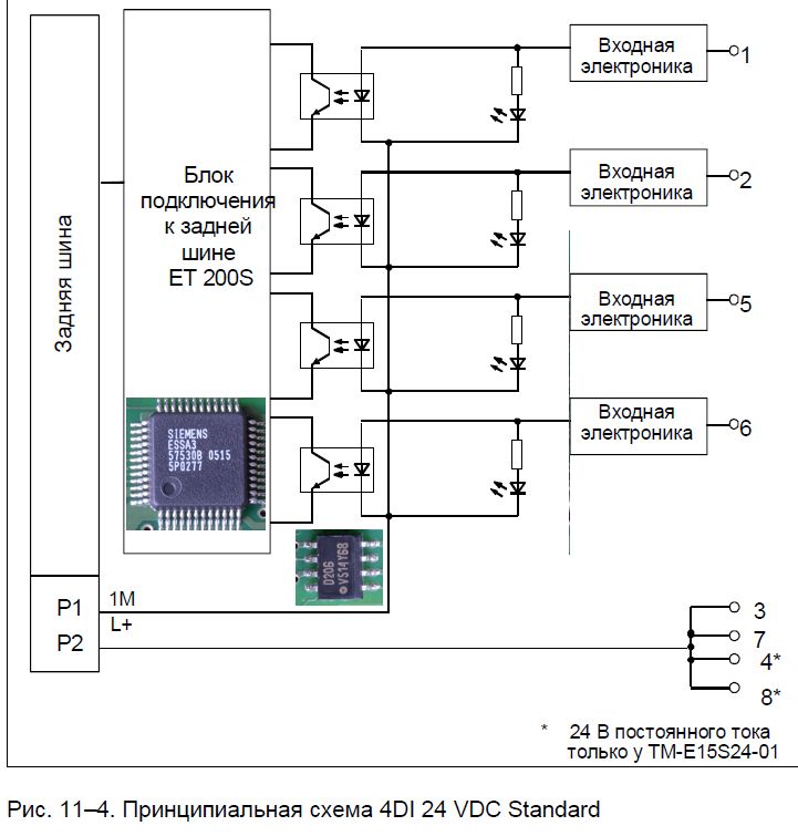
8 parallel PD9-1C max.

Rx1 rc plus wiring diagram. ET Systems RX1-RC DUAL. This page holds wiring details for various RF transmitter receiver and transceiver modules for 433 mhz 868mhz and 24 Ghz. Circuit board wiring diagram for rc wiring diagram centre.
Place jumper shorts across all three the P L and D pairs of pins. Wiring diagram for Indoor 180-R optional. 8 parallel PD4N-1C max.
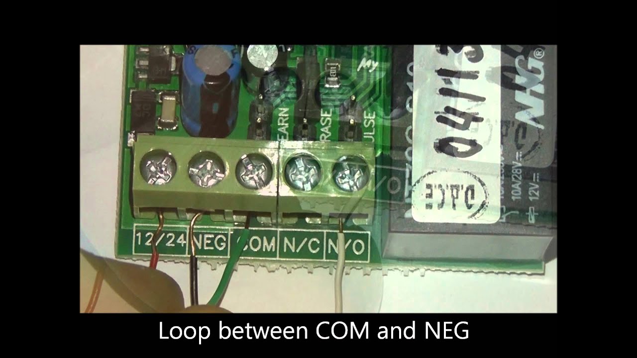
Wiring of the distribution board consumer unit with rcd 2 nos. 8 parallel optional T1 NO button manual switching. WIRING CAPACITORS RESISTORS SEMICONDUCTORS Table 1 Standard Elementary Diagram Symbols contd Iron Core Air Core Auto Iron Core Air Core Current Dual Voltage Thermal Magnetic Single Phase 3-Phase Squirrel Cage 2-Phase 4-Wire Wound Rotor Armature Shunt Field show 4 loops Series Field show 3 loops Commutating or Compensating Field show 2 loops.
When you insert the ESS ONE into a PC RC Plus will run and connect the device automatically. Function Description for RC PLUS Product information and firmware updating. Plumber has supplied the Danfoss.
- Cams may have compatibility problems with CAM Control feature Dont ask for help here. Place jumper shorts across all three the P L and D pairs of pins. Solder RX wire from Crossfire to Sbus pad.
12 Volt Relay Wiring Diagram - Collections Of Best Relay Wiring Diagram 5 Pin Bosch Endearing Enchanting Blurts. Wait for buzzer to finish beeping intermittently and remain on permanently - 15sec Remove the jumper shorts and power down. S1 switch for permanent light T1 NO button manual switching additionally possible RC RC-suppression kit if required Wiring diagram for RC-plus next max.
Architectural wiring diagrams play a part the approximate locations and interconnections of receptacles lighting and surviving electrical services in a building. 5 parallel LC-plus max. 8 parallel Wiring diagram for Indoor 180-R max.
2 parallel PD3N-1C max. - Inverter 3 must be activated Default beyond 320-RC5. 5 parallel LC-plus max.
Hvac Fan Relay Wiring Diagram. To get the crsf protocol to work you need to use the same UART. 5 parallel LC-Click-N max.
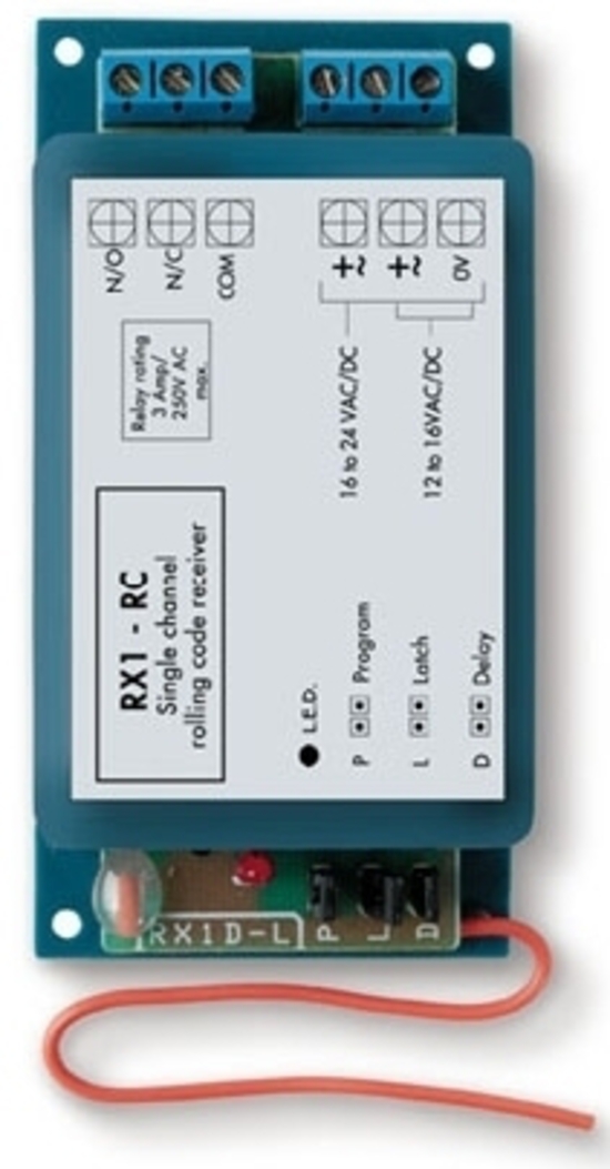
40355MHz optional Operating voltage 12-24V ACDC. Solder TX wire from Crossfire to TX1 pad on the back side of the FC 3. NO NC 31 transmitter locations.
SBUS SmartPort SmartAudio or Tramp CAMOSD control. Toy car transmitterL1same as L4 L215 turns 5mm wire 5mm diameter L335 turns 5mm wire 5mmdiameter. The wiring diagrams can not be found hence my involvement.
12 Volt Wiring Diagram Best 12v Relay Pin 5 and Roc Grp org In. ESS-ONE can communicate with the RC Plus software through the S-Link. Best Bosch Relay Wiring Diagram 5 Pole Electrical Outlet Symbol 2018.
You could change the name of your device through RC Plus to give it its own name. Set UART 1 as crossfire. Clipsal rc and 4rc series residual current device wiring diagrams 1 2 main switch single phase e 3n 4n clipsal rcbm 4rcbm and 4rcbe series combined mcbrcd wiring diagram a warning combined max.
Toy car receiverL49 turns 15mm wire on 45mm diameter tunable ferrite coil former. Diagram and instructions that come with my new Danfoss RET-B-RF RX1 And the Y Plan diagram I dont have a room stat fitted at present. Operating voltage 12-24V ACDC Single relay output.
Master transmitter function for the adding of additional transmitters. Wait for buzzer to finish beeping intermittently and remain on permanently -. RFLink Wiring Details.
2 parallel LC-Mini max. 5 parallel LC-Click max. Master Erase Factory default Power down.
If you have wiring diagrams for other modules that you used with RFLink send a mail with details and we will add it. You connect channel 2 to tx1 on the bottom and channel 1 to the sbus pad which is rx1. ET Systems RX1 -RC Code Hopping Receiver 1 channel 31 TX capacity Master remote feature Add extra remote from exisitng remote Audible buzzer 12v-24v acdc Like this.
PROGRAMMING THE RX1-RC DUAL Master-erase reset to factory default 1. NO NC 10 independent codes memory Removal of individual transmitters transmitter to be removed required Audible programming indication Memory full. RX1 Receiver 1 1 1 FP715Si Programmer 1 1 1 1 TS715Si Timeswitch 1 1 WC4B Wiring Centre 1 1 1 1 1 1 1 Order No 087N6500V4 087N6500CB 087N6500V3 087N6500V5 087N6518CG 087N6517DG 087N6520DG Page 16 20 14 22 18 24 12 Wireless Room Thermostats including Set Solution with RX1 Receiver Battery Powered Dial-setting Programmable With LCD 24 Hour 52.
RX1-DL PLUS 434MHz Features. Interconnecting wire routes may be shown approximately where particular receptacles or fixtures must be upon a common circuit. ASGARD V2 Example 1.
Superregenerative receiverbuilt by GE labs - sent by Trevor M0MUG. Wiring diagram for RC-plus next max.

Rx1 Rc Rx3 2017 Rc Dual Rolling Code Receivers Securitek

Rx1 Rc Rx3 2017 Rc Dual Rolling Code Receivers Securitek

Et Rx1 Single Channel Receiver Rsec

Rx Y Tx Etsystem Youtube
Connecting An External Receiver Youtube

Kendali Lampu Rumah Dengan Rf Wireless 4 Channel Nyebarilmu

Rx3 Rc Dual Et Systems Youtube

Italika Motorcycles Manual Pdf Wiring Diagram Fault Codes
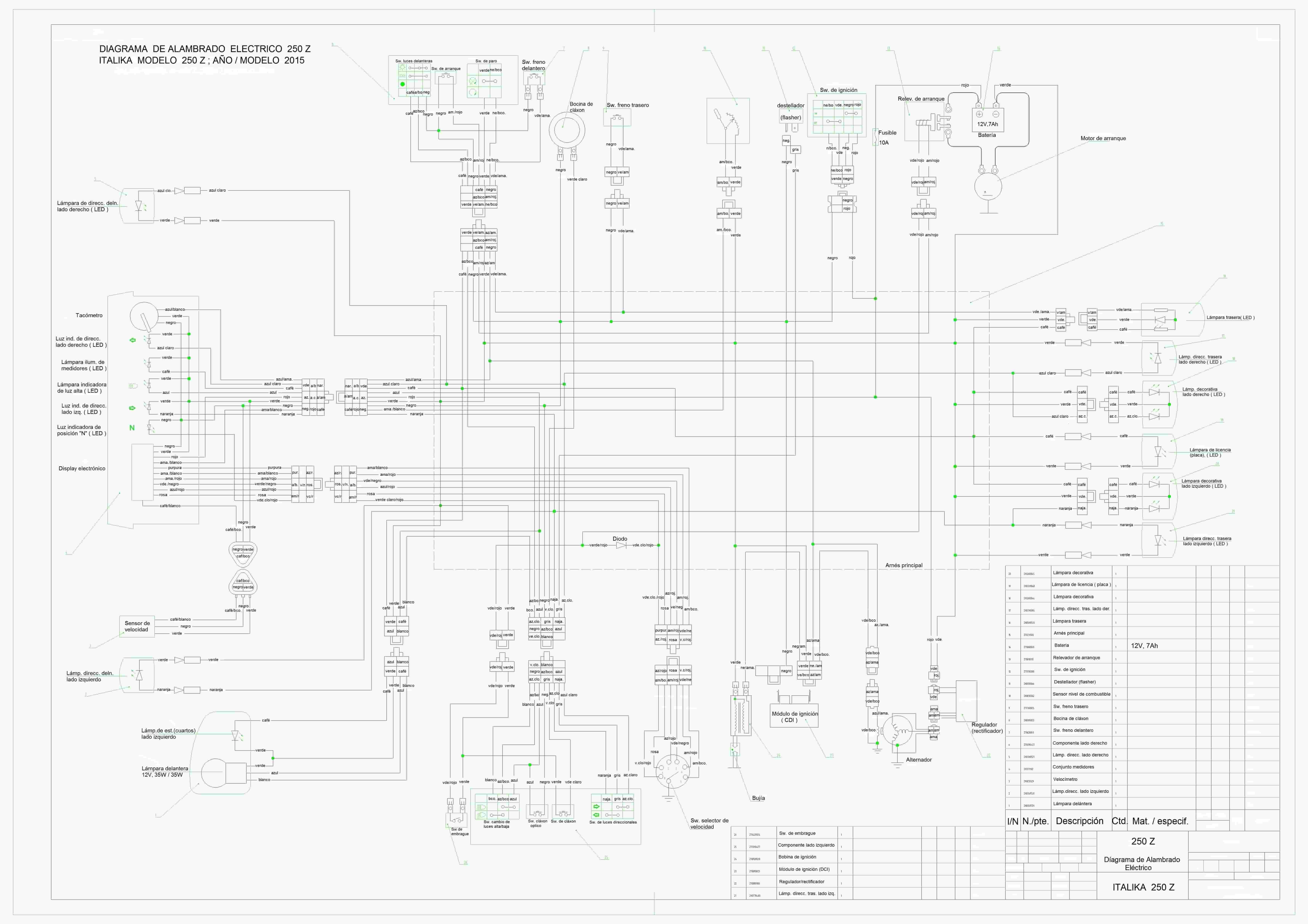
Italika Motorcycles Manual Pdf Wiring Diagram Fault Codes

Kendali Lampu Rumah Dengan Rf Wireless 4 Channel Nyebarilmu

Diagram Wiring Diagram Revo Fi Full Version Hd Quality Revo Fi Diagramhs Segretariatosocialelatina It
Et Rx1 Rc Gate Drive Solutions

Italika Motorcycles Manual Pdf Wiring Diagram Fault Codes
Diagram 64 Et Wiring Diagram Full Version Hd Quality Wiring Diagram Dmdiagram Amicideidisabilionlus It
First Time Drone Build Wiring Diagram Sanity Check Help Me Not Fry Everything Plz Diydrones
Receivers Mosco Electronics

Pin On Wiring Diagrams

Library

Library